
Home
/
Surenoo Graphic LCD Module >> 12864 Display Series
/
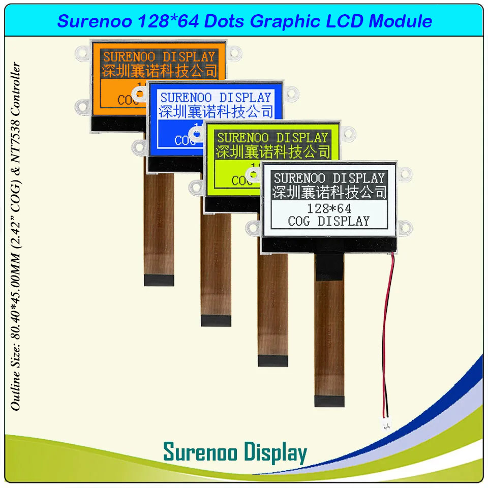
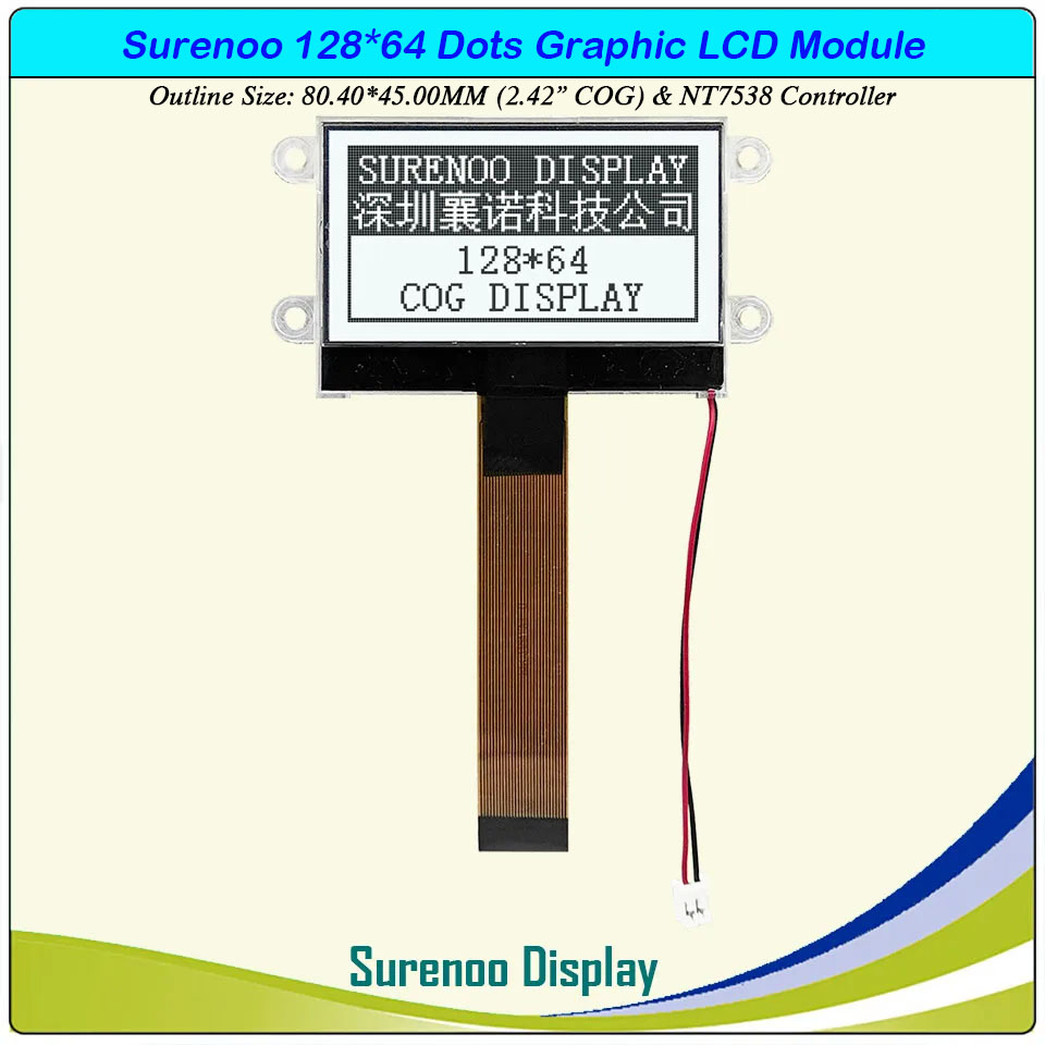
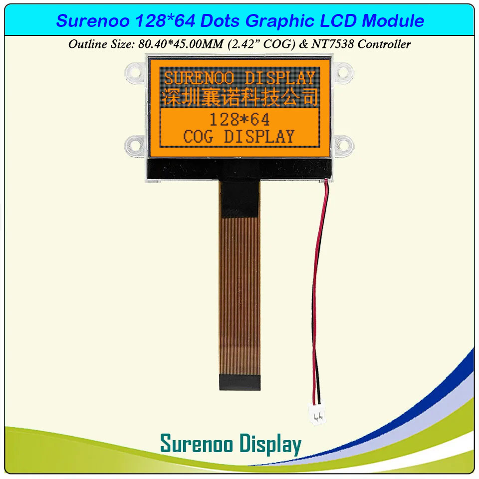
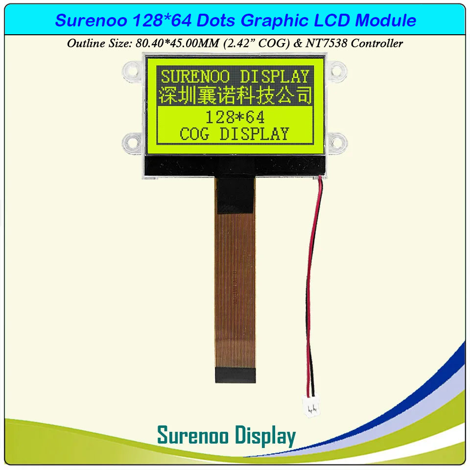
SLG12864P Outline=80.40X45.00MM 2.42" 12864 128X64 Surenoo COG Graphic LCD Module Display Screen Panel 8080 8-Bit Parallel NT7538 Controller STN Yellow Green Blue Negative FSTN Positive White LED Backlight for MCU 8051 PIC AVR ARM Arduino
SLG12864P Outline=80.40X45.00MM 2.42" 12864 128X64 Surenoo COG Graphic LCD Module Display Screen Panel 8080 8-Bit Parallel NT7538 Controller STN Yellow Green Blue Negative FSTN Positive White LED Backlight for MCU 8051 PIC AVR ARM Arduino
WISHLIST
Model No.: SLG12864P (2.42" COG)
Display Format: 128*64 Dots
Outline Size: 80.40X45.00MM
Controller: NT7538 or Equal
Display Format: 128*64 Dots
Outline Size: 80.40X45.00MM
Controller: NT7538 or Equal
8 sold
Quantity
-
Detail
- Overview
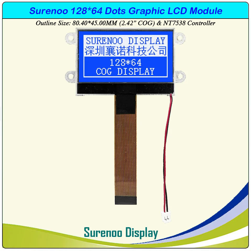
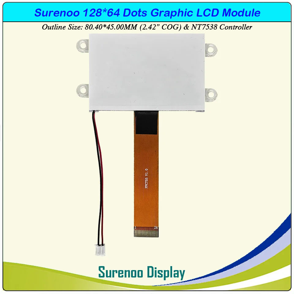
SLG12864P is a 2.42" 128*64 COG Monochrome Graphic LCD Module, NT7538 Controller standard 28P/0.5 12864 COG Graphic LCD Module.
SLG12864P supprot 8080 MCU Parallel interface, wide operating temperature range, rohs compliant. 3.3V power supply in default.It's easily controlled by MCU such as 8051, PIC, AVR and ARM. It can be used in any embedded systems, industrial device, security, medical and hand-held equipment.- Specification
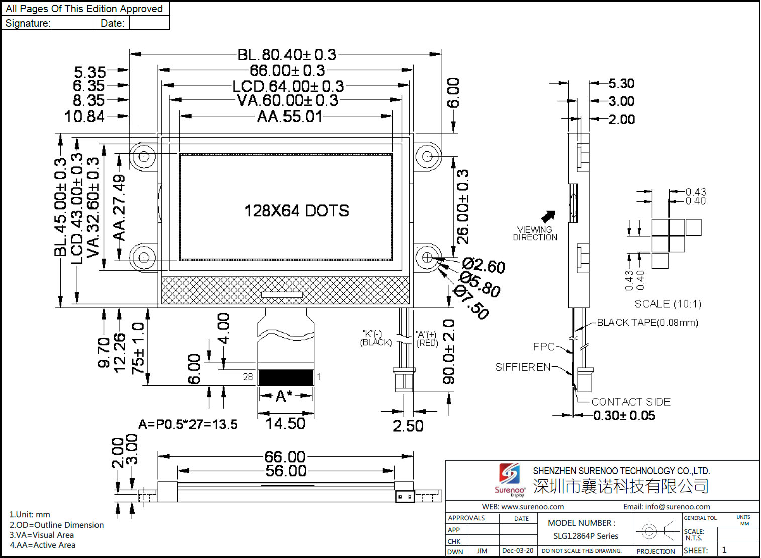
Gross Weight 0.040Kg Manufacturer Surenoo Display Type Graphic LCD Module Continuity Supply More than 10 years Part No. SLG12864P (2.42") Display Format 128*64 Dots Interface 8080 8-Bit Parallel IC or Equivalent NT7538 or Equal Voltage 3.3V in default Connection 1X28P/0.5 FPC & 2P/2.54 Connector Outline Dimension 80.40(W)x45.00(H)x5.30(T)mm Visual Area 60.00x32.60mm Active Area 55.01x27.49mm Display Type STN Yellow Green, STN Blue Negative, FSTN Positive Backlight Type (LED) Yellow Green, Orange, White IC Package COB Viewing Direction 6:00 O'Clock Operating Temperature-10℃~60℃Storage Temperature-20℃~70℃- Outline Drawing
- Interface
Pin No. Symbol Level Description 1 CS1 L Chip Select Input Pin, Active Low 2 RES L When /RST is "L", initialization is executed 3 A0 H/L Register select input pin, A0 = "H": Indicates that "A0" are display data, A0 = "L": Indicates that "A0" are control data 4 WR H/L Write signal. Active Low 5 RD H/L When connected to an 8080 MPU, this is Read signal. Low active. 6-13 DB0-DB7 H/L Data bus DB0~DB7 14 VDD +3.0V Power supply for Logic 15 VSS 0V Ground 16 Vout - DC/DC converter. Connect a capacitor to ground 17 CAP3+ - DC/DC converter.
Connect a capacitor between CAP3+ and CAP1-
Connect a capacitor between CAP1- and CAP1+18 CAP1- - 19 CAP1+ -- 20 CAP2+ - DC/DC converter.
Connect a capacitor between CAP2+ and CAP2-21 CAP2- - 22-26 V1-V4, V0 - Voltage levels for LCD, Connect a capacitor to ground 27 NC - No Connection 28 IRS H/L This terminal selects the resistors for the V0 voltage level adjustment.
IRS = “H”: Use the internal resistors
IRS = “L”: Do not use the internal resistors. The V0 voltage level is regulated by an external resistive voltage divider attached to the VR terminal29(Red) A +3.0V Anode of LED Backlight 30(Black) K 0V Cathode of LED Backlight - Documents
No. Item Document Name File Type ICON Date Description Mark 1 Datasheet 128X64 Graphic LCD Module Datasheet PDF 
2013-03-17 Standard 12864 Graphic LCD Module 2 Controller Controller IC NT7538 Datasheet PDF 2008-09-24 Graphic LCD Controller: NT7538 -
Customer ReviewsNo comments