
Home
/
Surenoo Graphic LCD Module >> 320240 Display Series
/
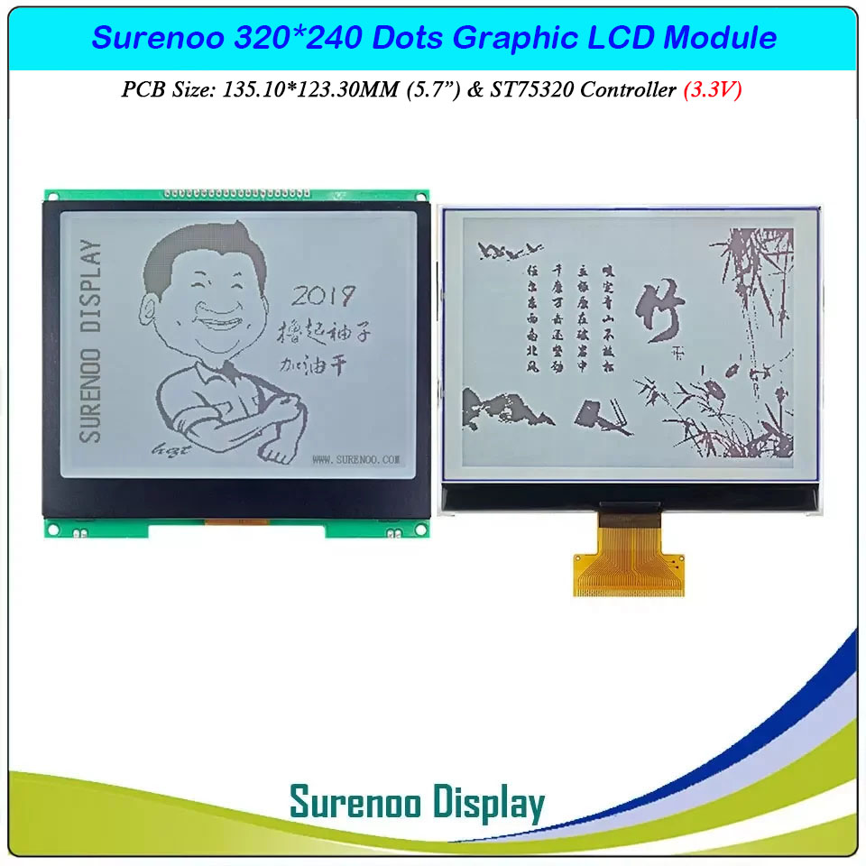
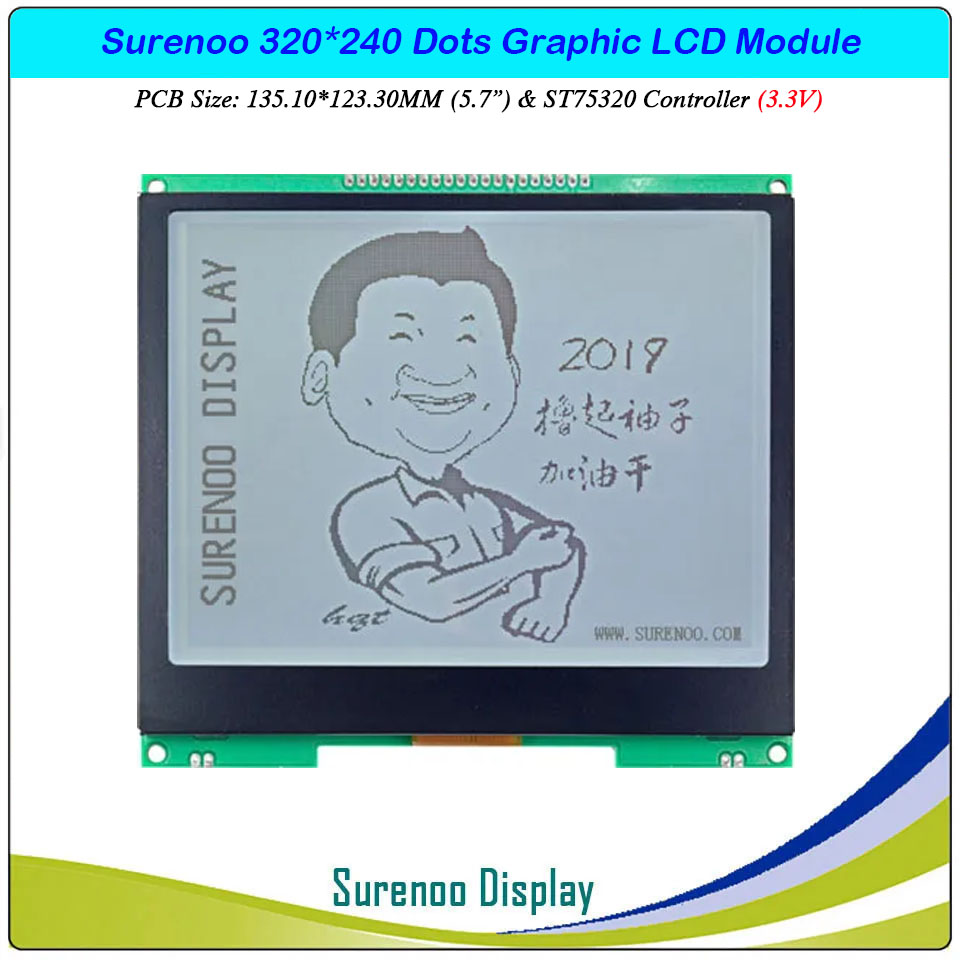
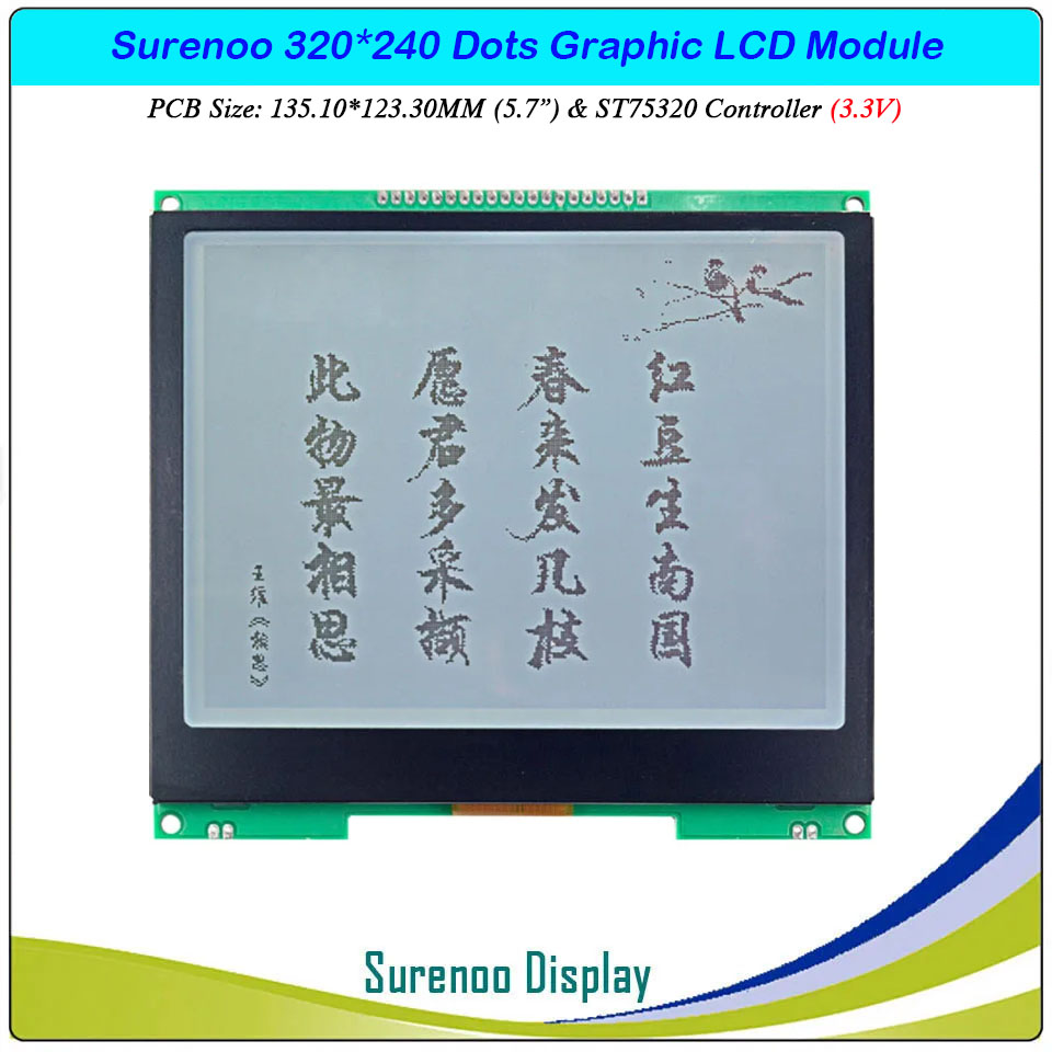
SLG320240F AA=115.17*86.37MM 5.7" inch 320240 320X240 320*240 Surenoo Graphic LCD Module Display Screen Panel 6800 8-bit MPU Parallel Serial SPI ST75320 COG Controller FSTN Positive LED White Backlight
SLG320240F AA=115.17*86.37MM 5.7" inch 320240 320X240 320*240 Surenoo Graphic LCD Module Display Screen Panel 6800 8-bit MPU Parallel Serial SPI ST75320 COG Controller FSTN Positive LED White Backlight
WISHLIST
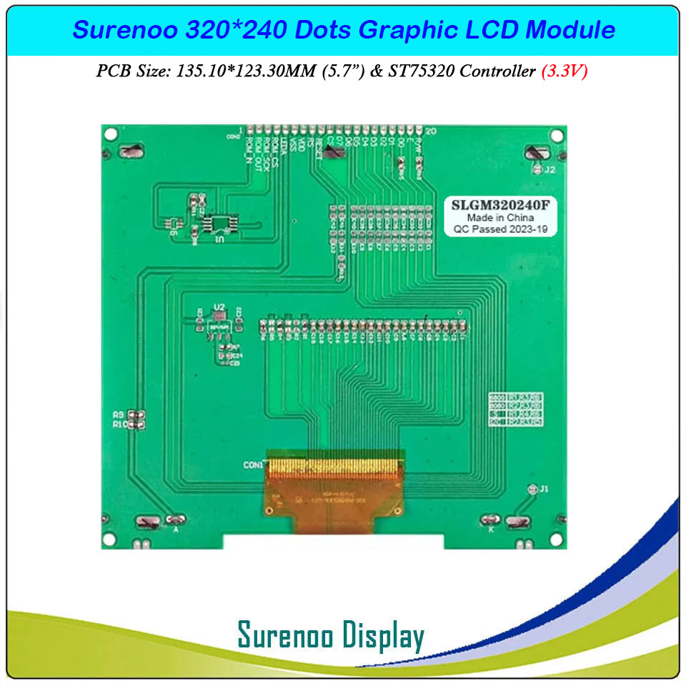
Model No.: SLG320240F (5.7")
Display Format: 320*240 Dots
PCB Size: 135.10X123.30MM
Driver: ST75320 or Equal
Display Format: 320*240 Dots
PCB Size: 135.10X123.30MM
Driver: ST75320 or Equal
8 sold
Quantity
-
Detail
- Overview
SLGM320240F is a 5.7" 320*240 dots Monochrome Graphic LCD Module, ST75320 COG standard 1X20P/2.54 320*240 Parallel Graphic LCD Module, supprot 6800 8-Bit parallel & Serial SPI interface, wide operating temperature range, rohs compliant. 3.3V power supply in default and 5.0V is optional for bulk order.It's easily controlled by MCU such as 8051, PIC, AVR and ARM. It can be used in any embedded systems, industrial device, security, medical and hand-held equipment.- Specification
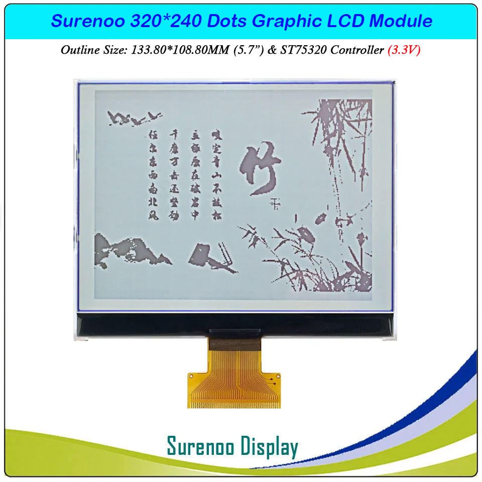
Gross Weight 0.240Kg Manufacturer Surenoo Display Type Graphic LCD Module Continuity Supply More than 10 years Part No. SLG320240F (5.7") Display Format 320*240 Dots Interface 6800 8-Bit Parallel / Serial SPI IC or Equivalent ST75320 or Equal Voltage 3.3V in default Connection 1X20P/2.54 Pin Header, 1X46P/0.8 FPC Outline Dimension SLGM320240F: 135.10(W)x123.30(H)x10.00(T)mm / SLGP320240F: 133.80(W)x108.00(H)x5.80(T)mm Visual Area 122.00x92.00mm Active Area 115.17x86.37mm Display Type FSTN Positive Backlight Type (LED/CCFL) White IC Package COG Viewing Direction 6:00 O'Clock Operating Temperature -20℃~70℃ Storage Temperature -30℃~80℃ - Outline Drawing

>> 2. SLGP320240F (Without PCBA)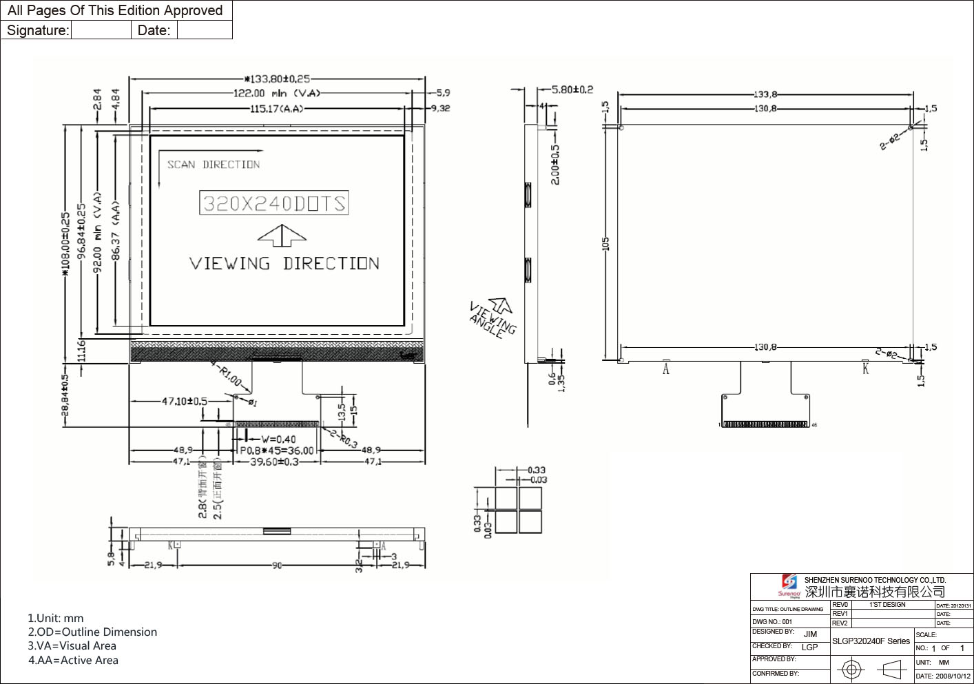
- Interface
Pin No. Symbol Level Description Parallel Serial Parallel Serial 1 ROM-IN - ROM Chip: Serial Data Input 2 ROM-OUT - ROM Chip: Serial Data Output 3 ROM-SCK - ROM Chip: Serial Clock Signal 4 ROM-CS - ROM Chip: Chip Selection Signal 5 LEDA 3.3V Backlight Anode (+3.3V) 6 VSS 0V Ground 7 VDD 3.3V Power Supply for Logic 8 RS (A0) H/L Instruction / Data Selection 9 RES L Reset Signal, Low Active 10 CS L Chip Selection Signal, Low Active 11-14 DB7-DB4 VDD - Data Bus Line Connect to VDD 15-17 DB3-DB1 SDA H/L Data Bus Line Serial Data Signal (DB3-DB2-DB1 Connect together) 18 DB0 SCLK H/L Data Bus Line Serial Clock Signal 19 E VDD - Enable Signal Connect to VDD 20 R/W VDD H/L H: Read Signal / L: Write Signal Connect to VDD
>> 2. SLGP320240F (Without PCBA)
Pin No. Symbol Level Description Parallel 4-Wire SPI IIC Parallel Serial 1 CS: L CS: L CS: H L Chip Selection Signal, Low Active Chip Selection Signal, Low Active 2 RST: L RST: L RST: L L Reset Signal, Low Active Reset Signal, Low Active 3 A0 (RS) A0 (RS) A0 (RS): H H/L H=Data, L=Command Selection SPI: H=Data, L=Command Selection
IIC: Connect High Level4 R/W (WR) H H I/O 6800: H=Read Signal, L=Write Signal Connect High Level 5 E (RD) H H - 6800: Enable Signal Connect High Level 6 D0 SCLK SCLK - Data Bus Line Serial Clock Signal - 7-9 7-9 7-11 - Data Bus Line Serial Data Signal
SPI: 7-9 Pin Connect together
IIC: 7-11 Pin Connect togetherD1-D3 SDA SDA - 10-13 10-13 12-13 - Data Bus Line SPI: 10-13 Pin Connect High Level
IIC: 12-13 Pin Connect High LevelD4-D7 H H 14 VSS VSS VSS Ground Power Ground Power Ground 15 IF2: L IF2: L IF2: H - - 16 IF1: H IF1: H IF1: H - - 17 IF0: L IF0: H IF0: L - - 18 VD1 H Power Supply for the enable internal digital circuits 19-20 VDD 3.3V Power Supply for Logic 21 VSS Ground Power Ground 22 VC Multi-Voltage Circuit Connect Capacitance between VC and VSS 23 V2 Multi-Voltage Circuit Connect Capacitance between V2 and VSS 24 V1 Multi-Voltage Circuit Connect Capacitance between V1 and VSS 25 MV1 Multi-Voltage Circuit Connect Capacitance between MV1 and VSS 26 MV2 Multi-Voltage Circuit Connect Capacitance between MV2 and VSS 27 AVDD Multi-Voltage Circuit Connect Capacitance between AVDD and VSS 28 CA1P Multi-Voltage Circuit Connect Capacitance between CP1P and CP1N 29 CA1N Multi-Voltage Circuit 30 CA2P Multi-Voltage Circuit Connect Capacitance between CP2P and CP2N 31 CA2N Multi-Voltage Circuit 32 CD1P Multi-Voltage Circuit Connect Capacitance between CD1P and CD1N 33 CD1N Multi-Voltage Circuit 34 NVDD Multi-Voltage Circuit Connect Capacitance between NVDD and VSS 35 CD2N Multi-Voltage Circuit Connect Capacitance between CD2P and CD2N 36 CD2P Multi-Voltage Circuit 37 MV3 Multi-Voltage Circuit Connect Capacitance between MV3 and VSS 38 CB1N Multi-Voltage Circuit Connect Capacitance between CB1P and CB1N 39 CB1P Multi-Voltage Circuit 40 V3 Multi-Voltage Circuit Connect Capacitance between V3 and VSS 41 CE1P Multi-Voltage Circuit Connect Capacitance between CE1N and CE1P
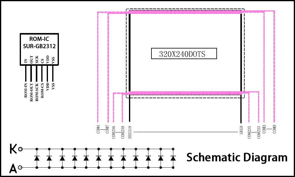
Connect Capacitance between CE3P and CE1N42 CE1N Multi-Voltage Circuit 43 CE3P Multi-Voltage Circuit 44 CE2N Multi-Voltage Circuit Connect Capacitance between CE2P and CE2N 45 CE2P Multi-Voltage Circuit 46 VOUT Multi-Voltage Circuit Connect Capacitance between VOUT and VSS - Schematic Diagram
- Documents
No. Item Document Name File Type ICON Date Description Mark 1 Datasheet 320X240 Graphic LCD Module Datasheet PDF 
2013-03-17 Standard 320240 Graphic LCD Module 2 Controller Controller IC ST75320 Datasheet PDF 2008-09-24 Graphic LCD Controller: ST75320 -
Customer ReviewsNo comments