
Home
/
Surenoo Graphic LCD Module >> Others Dots (25664 / 32064 / 128128 / 160128 / 160160 / 240160 / 384160)
/
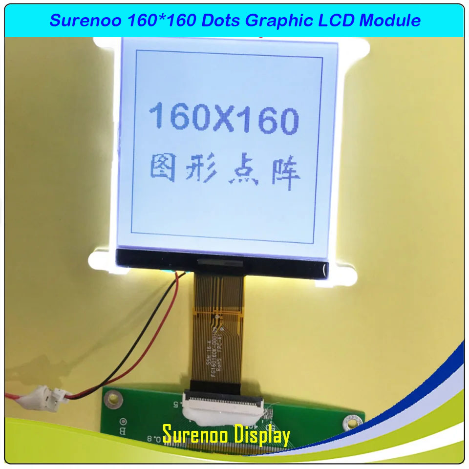
SLG160160A Outline=83.80X76.50MM 3.0" 160160 1600X160 160*160 Surenoo Graphic LCD Module Display Screen Panel 8080 8-Bit Parallel UC1698U Controller FSTN Positive LED Backlight for 8051 PIC AVR ARM
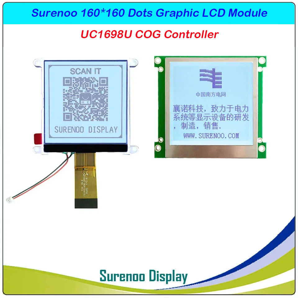
SLG160160A Outline=83.80X76.50MM 3.0" 160160 1600X160 160*160 Surenoo Graphic LCD Module Display Screen Panel 8080 8-Bit Parallel UC1698U Controller FSTN Positive LED Backlight for 8051 PIC AVR ARM
WISHLIST
Model No.: SLG1600160A (SLGM160160A / SLGP160160A) (3.0")
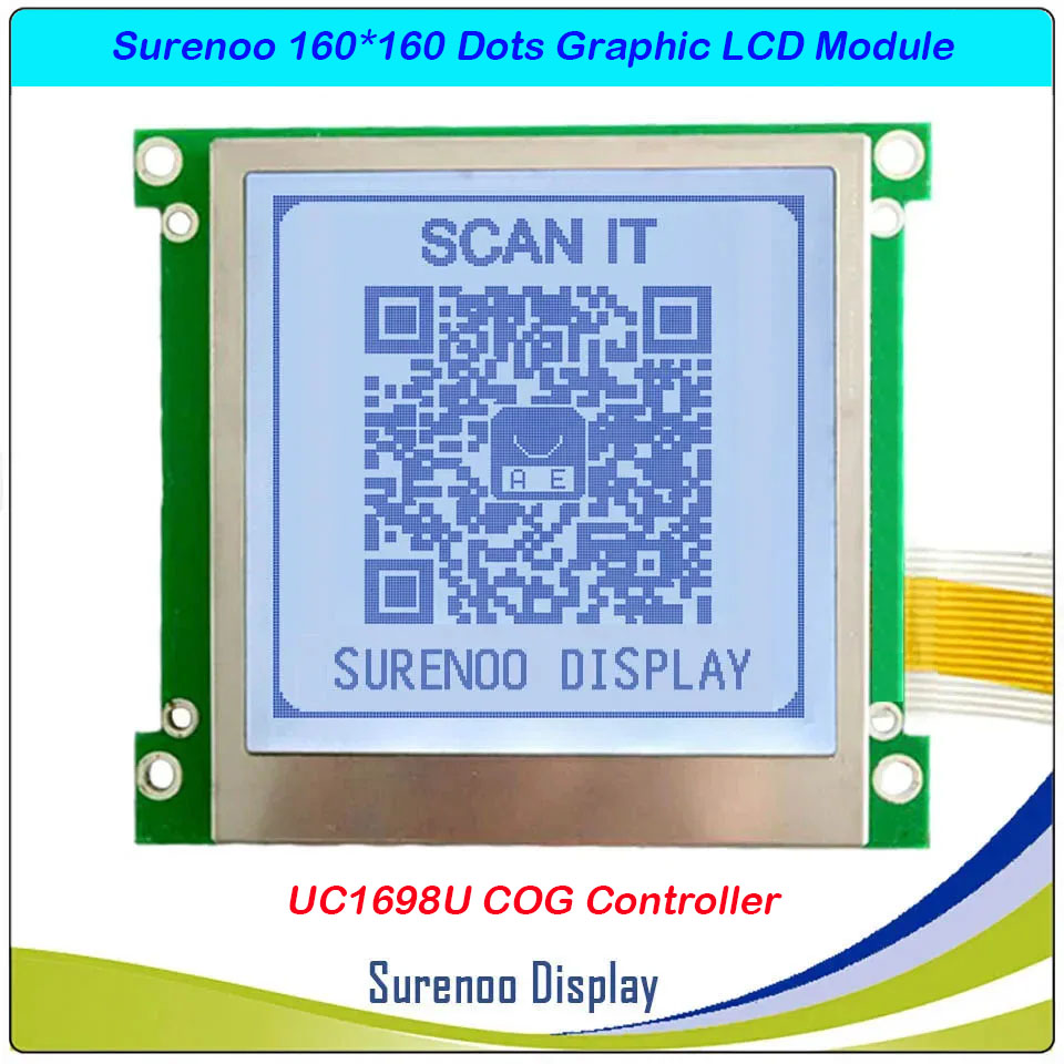
Display Format: 160*160 Dots
PCB Size: 83.80X76.50MM
Controller: UC1698U or Equal
Display Format: 160*160 Dots
PCB Size: 83.80X76.50MM
Controller: UC1698U or Equal
4 sold
Quantity
-
Detail
- Overview
SLG160160A is a 3.0" 160*160 dots Monochrome Graphic LCD Module, UC1698U COG Graphic LCD Controller standard 18P/1.0 FFC 160*160 parallel Graphic LCD Module, supprot 8080 8-Bit parallel interface, wide operating temperature range, rohs compliant. 3.3V power supply in default and 5.0V is optional for bulk order.It's easily controlled by MCU such as 8051, PIC, AVR and ARM. It can be used in any embedded systems, industrial device, security, medical and hand-held equipment.- Specification
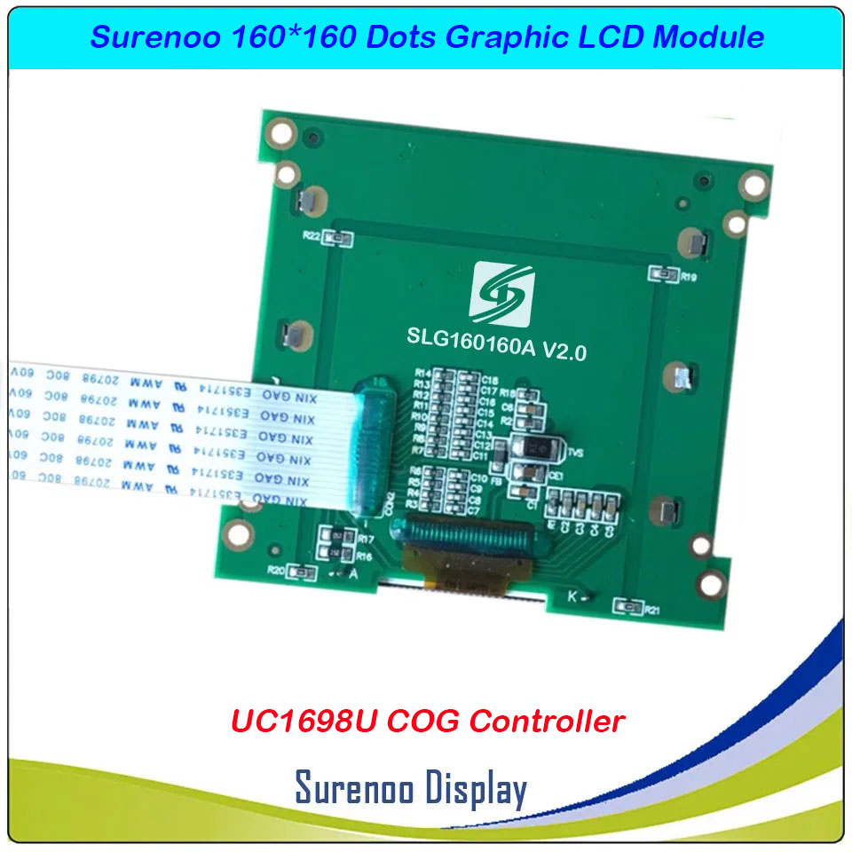
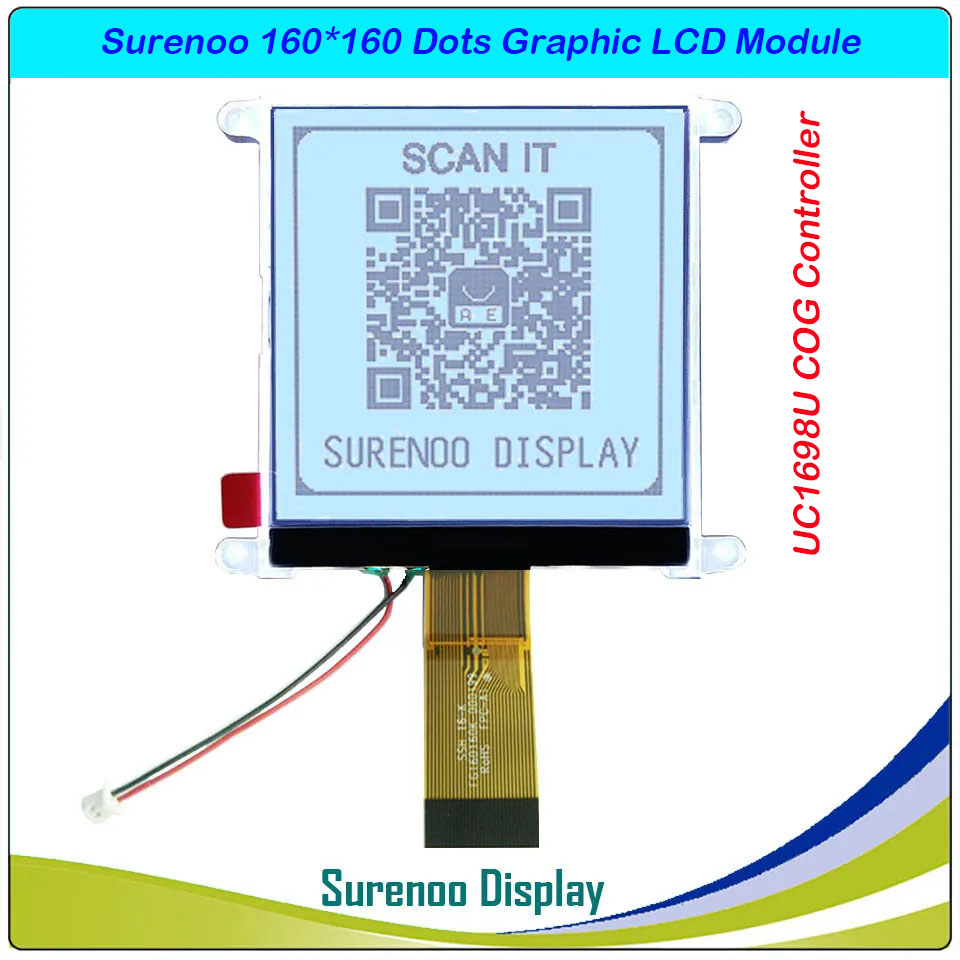
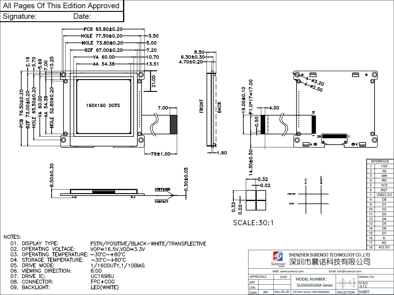
Gross Weight 0.080Kg Manufacturer Surenoo Display Type Graphic LCD Module Continuity Supply More than 10 years Part No. SLG160160A (SLGM160160A / SLGP160160A) Display Format 160*160 Dots Interface 6800 8-bit Parallel IC or Equivalent UC1698U or Equal Voltage 3.3V in default Connection 1X18P/1.0 FFC; 30P/0.5 FPC Outline Dimension SLGM160160A: 83.80(W)x76.50(H)x8.50(T)mm; SLGP160160A: 80.00(W)x72.50(H)x5.00(T)mm Visual Area 60.00x60.00mm Active Area 54.38x54.38mm Display Type FSTN Positive Backlight Type (LED) White IC Package COG Viewing Direction 6:00 O'Clock Operating Temperature-20℃~70℃Storage Temperature-30℃~80℃- Outline Drawing
2. Model No.: SLGP160160A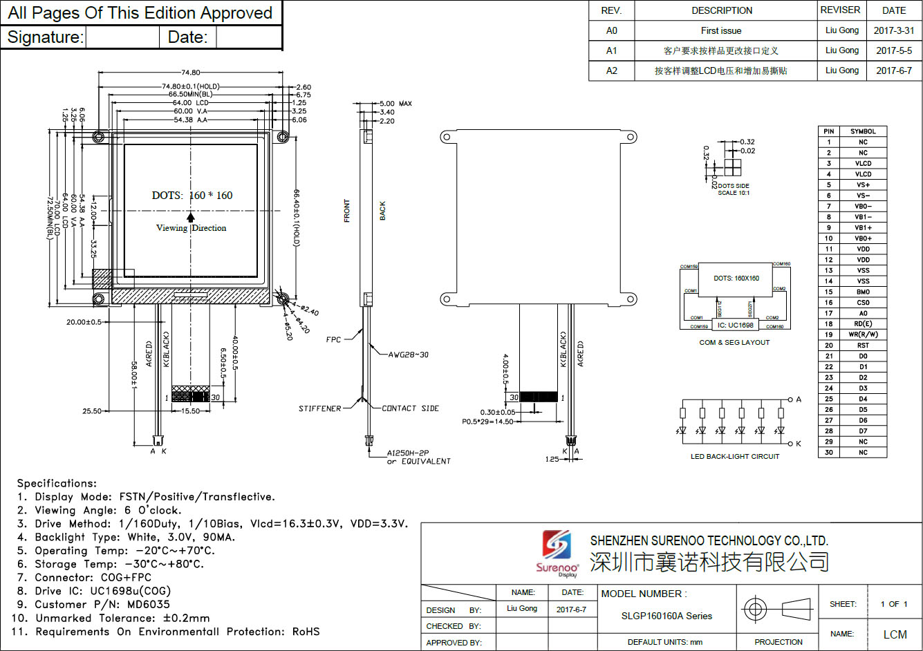
- Interface
Pin No. Symbol Description Model No.: SLGM160160A 1 VSS Power Ground 2 CD Control / Display Pin: ”L”: Control data, ”H”: Display data 3 WR Write Signal, Active-Low 4 RD Read Signal, Active-Low 5 CS Chip Selection, Active-Low 6 RST Reset Signal, Active-Low 7 VDD Logic Power Supply 8-15 DB0-DB7 Data Bus Line 17 Busy Controller Busy Signal, MPU should poll this signal before accessing the LCD module 18 BLK Backlight Cathode 19 NC No Connection 20 BLA Backlight Anode Model No.: SLGP160160A 1-2 NC No Connection. 3-4 VLCD High voltage LCD Power Supply. When internal VLCD is used, connect these pins together. When external VLCD source is used, connect external VLCD source to VLCDIN, pins and leave VLCDOUT open. 5 VS+ LCD Bias Voltages. These are the voltage sources to provide SEG driving currents. These voltages are generated internally. Connect capacitors of CAX / CBX value between VAX+ / VBX+ and VAX– / VBX–, respectively. 6 VS- 7 VB0- 8 VB1- 9 VB1+ 10 VB0+ 11-12 VDD Power supply for LCD circuit. 13-14 VSS Ground. 15 BM0 Bus Mode: The interface bus mode is determined by BM0 with the following relationship: BM0 Mode I 6800/8-bit 0 8080/8-bit 16 CS0 Chip Selection. Chip is selected when CS0 = “L”. When the chip is not selected, DB [7:0] will be high impedance. 17 A0(CD) Selects Control data or Display data for read/write operation. In S9 mode, CD pin is not used. Connect to VSS when not used.
”L”: Control data ”H”: Display data18 WR1(RD) WR[1:0] control the read/write operation of the host interface. See section Host Interface for more detail.
In parallel mode, the meaning of WR[1:0] depends on whether the interface is in the 6800 mode or the 8080 mode. In serial interface modes, these two pins are not used, connect them to VSS.19 WR0(WR) 20 RST When RST=”L”, all control registers are re-initialized by their default states. Since UC1698u has built-in Power-ON reset and software reset commands, RST pin is not required for proper chip operation. An RC Filter has been included on-chip. There is no need for external RC noise filter. When RST is not used, connect the pin to VDD. 21-28 DB0-DB7 Data Bus Line 29-30 NC No Connection - Documents
No. Item Document Name File Type ICON Date Description Mark 1 Datasheet 160X160 Graphic LCD Module Datasheet PDF 
2013-03-17 Standard 160160 Graphic LCD Module 2 Controller Controller IC UC1698U Datasheet PDF 2008-09-24 Graphic LCD Controller: UC198U -
Customer ReviewsNo comments